
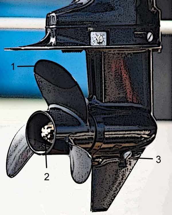
Prop and lower unit care should be at the top of every boater’s maintenance list. After all, they are what make your boat go. If they break down, you are dead in the water. Fortunately, maintaining your boat’s prop and lower unit takes only a few minutes, and you need only a few tools. Use this guide to make inspecting and maintaining your boat’s prop and lower unit fast and easy.
How to Inspect a Boat Propeller
Regular inspection prevents vibration, shaft damage, fuel inefficiency, and hub failure.
Tools & Equipment:
- Propeller wrench, marine grease (2-4-C or equivalent), torque wrench.
- Pliers to remove the cotter pin.
- 1 1/16″ deep socket with a breaker bar.
- Scrap piece of 2″ x 4″.
Step-by-Step Instructions:
Visual Blade Inspection: Check all blades for bent tips, nicks, cracks, or missing chunks. Damaged blades cause severe vibration and wear on the bearings.
Remove Propeller: Unbolt the prop nut, remove the prop, and clean the shaft splines.
- Safety First: Disconnect the engine kill-switch lanyard and/or disconnect the battery negative lead to prevent accidental engine starting.
- Remove the cotter pin from the nut.
- Wedge the 2″ x 4″ between the bottom of the anti-ventilation plate and a prop blade to keep the prop from spinning.
- Place the socket on the nut and use the breaker to loosen the nut. Prop nuts are torqued to around 55 ft-lbs, so it will be tight.
Inspect Rubber Hub / Drive Sleeve: Examine the inner prop hub for slippage, burnt rubber, or cracked plastic inserts.
- Remove the nut and washers. Caution: The washers go on in a specific order. Take a picture with your phone of the order they came off in, then place them on a rag in the proper order to ensure you put them back on in the same order.
- Remove the hub and inspect it for salt, dirt, or damage. Wipe with a clean rag to remove old grease and contaminants.
Inspect Shaft Straightness: Spin the shaft slowly by hand to confirm it is straight and unbent. Inspect the prop shaft for damage, salt, or dirt. Pay close attention to the splines. Wipe with a clean rag to remove old grease and contaminants.
Check For Fishing Line Behind The Prop
Look for fishing line wrapped around the prop shaft. It will accumulate between the hub and the lower unit seal. Fishing line can get under the seal and damage it. A damaged seal will allow water into your gear case, destroying the gears and bearings. Remove all fishing line. If it has gotten underneath the seal, carefully pull it out while unwinding it from around the shaft.
Monofilament and braided line can wrap around the propeller shaft, heat from friction, and cut through the prop shaft seals, causing lower unit oil leakage and catastrophic water intrusion.
Tools & Equipment
Needle-nose pliers/utility knife
Step-by-Step Instructions
- Inspect Shaft for Line: Carefully inspect the propeller shaft base, thrust washer seat, and rubber shaft seal for wrapped fishing line.
- Remove Line: Use needle-nose pliers, a small pick, or a blade to unwind and clear all traces of monofilament or braid.
- Check Seal Integrity: Inspect the rubber prop shaft oil seal for cuts or tears. If oil is leaking, the seal is damaged. Replace the seal if oil is weeping or the line has melted into it.
- Clean & Grease Prop Shaft: Wipe the shaft clean of old debris and coat it generously with water-resistant marine grease to prevent seizing.
- Reinstall & Torque: Slide thrust washer, prop, and spacer onto shaft. Tighten the prop nut with a torque wrench to the manufacturer’s specification (typically 30–55 ft-lbs) and secure the locking tab/cotter pin.
How to Replace an Outboard Motor Impeller
The rubber impeller circulates water through the engine. Replace it annually or every 200 hours to prevent overheating and powerhead failure.
Tools & Equipment
- Socket set / open-end wrenches.
- Impeller repair kit (impeller, keyway, wear plate, housing gasket, O-rings)
- Marine grease/glycerin lubricant
Step-by-Step Instructions
- Shift to Neutral / Disconnect Battery: Set the shift lever to Neutral or Forward per manual specifications and disconnect the battery.
- Remove Lower Unit Bolts: Unbolt lower unit mounting bolts, including the trim tab hidden bolt. Gently slide the lower unit downward to free it from the driveshaft and shift shaft.
- Remove Water Pump Housing: Unbolt the 4 water pump housing bolts. Lift the housing straight up off the driveshaft.
- Remove Old Impeller & Key: Slide the old impeller up off the driveshaft. Remove the drive key (Woodruff key) from the driveshaft keyway.
- Replace Wear Plate & Gaskets: Clean the housing base, remove the old wear plate and gaskets, and install the new wear plate and base gaskets included in the kit.

Install New Impeller:
- Fit the new drive key into the driveshaft slot.
- Coat the inside and vanes of the new impeller with glycerin or dish soap.
- Slide the new impeller down the driveshaft over the drive key.
- Reinstall Housing: Lower the pump housing over the impeller while rotating the driveshaft clockwise so the impeller vanes bend in the correct rotation direction.
- Torque Bolts & Reinstall Lower Unit: Torque the housing bolts to spec. Apply marine grease to the driveshaft splines, avoiding the shaft’s top end.
- Reinstall the lower unit, align the shift shaft and driveshaft, and torque the bolts.
Servicing Outboard Motor Gear Case Oil
Changing gear lube annually or every 100 hours removes metallic wear particles and detects water contamination before gear failure.
Tools & Equipment
- Lower unit gear lube (SAE 80W-90 marine gear oil or manufacturer specification)
- Oil pump adapter
- Flathead screwdriver or hex socket
- Oil drain pan & fresh sealing gaskets/washers for plugs
Step-by-Step Instructions
- Vertical Alignment: Lower the motor to a vertical position to allow oil to drain completely.
- Position Drain Pan: Place an oil drain pan beneath the bottom lower unit drain/fill plug.
- Remove Drain Plug First: Unscrew the lower (drain) plug located near the bottom of the gear housing. Allow a few drops of oil to drip into your hand. Inspect the oil that dripped into your hand for color and metal shavings. See Inspect Drained Oil below.
- Remove Vent Plug: Unscrew the upper vent plug. Removing it breaks the vacuum and allows oil to drain freely.
Inspect Drained Oil:
Inspect the lower unit oil for water and metal shavings.
- Amber or dark clear oil indicates normal wear.
- Milky white or creamy oil indicates water contamination and blown seals. If the oil is milky, water has gotten into the gearbox. Repair the gearbox before major damage occurs.
- Excessive Metal Filings: Inspect the magnetic drain plug. Fine metallic paste is normal; large chunks indicate gear damage. Repair the gearbox.
- Pump Fresh Lube From Bottom: Attach the lower unit lube pump hose to the bottom drain hole. Pump gear lube upward until oil flows out of the top vent hole without air bubbles.
- Install Top Plug: Insert the vent plug with a new sealing gasket and tighten securely while the pump is still connected to maintain pressure.
- Install Bottom Plug: Remove the pump fitting from the bottom hole and quickly install the lower drain plug with a new gasket. Wipe down any spilled oil.
Flush The Cooling System
Flushing fresh water through the outboard removes salt, silt, sand, and debris that corrode water passages or cause overheating.
Tools & Equipment
- Flusher attachment (“ear muffs”) or direct hose flush adapter
- Garden hose with fresh water supply
- Ear protection (if engine is running)
Step-by-Step Instructions
- Position the Motor: Lower the motor to a vertical position so water can drain naturally.
- Attach Flushing Muffs: Slide the rubber flushing muffs over the lower unit’s water intake screens on both sides. Ensure a snug seal.
- Connect Hose & Turn On Water: Attach a garden hose to the muffs and turn on fresh water at full pressure before starting the engine. Make sure water overflows around the muff cups.
- Start the Engine: Start the motor in Neutral. Never shift into gear while flushing.
- Verify Water Flow: Check the telltale port (“pee hole”) on the powerhead. Water should stream out within a few seconds. If no water flows, shut down immediately.
- Flush for 5–10 Minutes: Run the engine at idle for 5 to 10 minutes to allow the thermostat to open and flush internal cooling passages thoroughly.
- Shut Down: Turn off the engine first, then turn off the garden hose and disconnect the muffs.
Corrosion Control Anodes
Sacrificial zinc or aluminum anodes protect lower unit metal and propeller shafts from galvanic corrosion.
Tools & Equipment
- Socket wrench/screwdriver, wire brush or emery cloth
- Replacement anodes (if body is >50% consumed)
Step-by-Step Instructions
- Locate Anodes: Identify lower unit anodes—commonly located on the trim tab above the prop, gearcase sides, and power bracket.
- Visual Inspection: Inspect each anode body. Check for pitting, flaking, or erosion.
- Determine Replacement Threshold: If the anode body is 50% or more eroded, replace it immediately.
- Clean Anode Contact Surface: If the anode is reusable, clean the oxide layer with a wire brush or sandpaper. Never paint anodes because paint insulates them and prevents sacrificial protection.
- Replace Corroded Anodes: Unbolt the eroded anode. Clean the metal mounting surface on the lower unit to ensure direct metal-to-metal electrical contact.
- Install New Anode: Bolt the new anode firmly in place. Verify electrical continuity with a multimeter if necessary.
Congratulations, you’re done!
Now you can hit the water with confidence that your prop and lower unit are in good shape. Below are two excellent videos that demonstrate how to inspect your prop and check for water in your gearcase.
Get more tips on maintaining your boat in our Boating How-To Guide!
Looking for other ways to spend more time on the water? Beat the summer heat, take the kids on a nighttime fishing trip, or rekindle romance with that special someone using LED underwater transom lights. Learn more by clicking Boat Lights at the top of this page.
How do you change the impeller
Hi Mike. That’s a good question. I’ve added a YouTube video that shows how to change the impeller on an outboard. It is a fast and easy job.
You don’t mention anything about cotter pins during disassembly .
much less reassembly
Thanks for pointing that out Jeff. I’ve added the information.